Uncategorized

Firing the ball.. at wood

Ok first attempts to fire the ball started.  The end result is that I need to design a ball guide.  Surprisingly while I was worried that the ball would shoot forward and have to compensate due to the angle of the standard ball trough I was repurposing, instead shoots backwards a bit.  Tried to capture some ‘slow motion’ videos but the reality is, the ball moves pretty fast.

Here can see it go backwards a bit.

And from a more frontal view, can see the dent the ball is making into the wood.

So have been working on a ball guide. Tried printing a bunch of cones but most success was just a block of wood this morning. 

So, progress.. 

Pinball

Closer to turret action

Ok so got the subways for the 360 done in the last post, so now have been trying to design/print the top size turret.    Got that printed today.

20170806_123059

I positioned my test jig over where this will all be placed on the game.  So, everything below the plywood will be under the plywood. in the game as well.

20170806_12325920170806_123306

The last piece of the puzzle (before software), is the ~2″ gap between the ball trough and the bottom of the turret piece.   Can see this gap at the end of the video I posted of the 360 degree action.

I’ve also been debating a new tool for the workshop to help this..  not sure if hobby CNC, welding rig, or just buy some more time at maker place is best approach.   Either way not sure plastic is going to cut it for this ramp and may need to do a little bit metal work regardless, we’ll see.

Uncategorized

A little movement

Ok have been bogged down trying to create subways (ramps underneath a playfield in pinball are called subways).  To feed a stock 8-ball trough that is normally used at a bottom of a playfield after your ball drains / it’s what stores all the balls.   I am using one in the center area to load up and then use as a ‘up-kicker’ to launch balls up through the hole in the lazy susan bearing I showed last time with the stepper motors.

The subways I designed were nearly too much for my Rigidbot 3D printer.. it has a 10x10x10″ build volume and the subways are about 11.5″ .. so took very creative placement to get them to print, and then had printer breakdowns, and trouble printing without warping, and it’s really hot in my garage in summer so limited interest.   But pushed through all that this weekend.

20170730_111053

So the idea here is that this will be mounted underneath the central flat section, and the white subway will be under the top of one players playfield and the grey will be at the same point for the opposite player.

20170730_111057

The Bottom here is just the stock part which has leave switches all along it.  This is so that it can count how many balls are loaded in at a time.   What isn’t shown here is the solenoid that will be mounted to fire the balls upward.  I’m upgrading the power of that solenoid to be stronger than the one used normally since we’ll need ~3-4″ of vertical height I think, but haven’t gotten much into that part yet as needed to get this sorted first.

I may very well remake this out of sheet metal.  I’m hoping I could use the CNC plasma cutter and sheet metal tools at makerplace to cut and then form these when the time comes.

Here’s a video of them showing that gravity works ok.

Uncategorized

Stepper motors

The pinball software framework I’m using didn’t yet have stepper motor support.  So in the last few weeks I’ve been working to glue a stepper motor board into the system.  Yesterday I got to the point where it’s in the framework and I got a unit test going.

The purple 3D printed gears mounted to a lazy susan bearing are the beginnings of the central mechanism that will be a 360 degree angry tiki ball turret.  

Uncategorized

Theme! Forbidden Island

Now that some of the nuts and bolts are over with, it’s probably a good time to start talking about theme.   I have been considering it to be kind of explorers on a island that is controlled by a kind of tiki god sort of thing.  Perhaps with different boss levels for the different elements (lava, water, wind, earth) .. something of that nature.

With opportunities for both player vs player and player vs game/bosses.   I don’t have some elaborate game tree right now.. so , for the moment… what I can provide is a ‘vision board’ … one of those hippy things where you post a bunch of pictures and that’s supposed to provide some level of focus / inspiration.

Also, I am not an artist.. I have no idea how to execute the art on this thing.  Will be a learning experience for sure, if I don’t cave and hire a starving artist or something.

Inspiration #1 is the old Fireball Island board game.  We had this when I was a kid, and it was fun.. circa 1986.  The gist was getting to the top of the mountain where there was this statue where if you rolled a bad card a red marble was released and that would roll down different channels in the game and knock your pieces over.

Anyways, this is what I was thinking about.  And, on my game I hope to build a rotating head that can spit pinballs out.. that will be the first technical / build a mechanism type challenge.  But, again.. this is about vision, not implementation.

Other inspirations..

I found this image in a click bait article at the bottom of CNN or something.  Looks like it was stolen from some game called “Viking: War of Clans” per Google reverse image searchunnamed

Additionally, I think also via some clickbait over to Atlas Obscura.. There are actually some real caves with cool faces all over it in Italy of all places.

http://www.atlasobscura.com/places/the-monsters-of-bomarzo

And last but not least, the Disneyland Enchanted Tiki Room

That’s about as far as I’ve gotten into it, but that’s the vision so far as it is.

Uncategorized

Test Cabinet Built and other progress


Happy to report that my time at MakerPlace was successful.  After running some router bit calibration patterns, really didn’t have too many problems cutting out the Test Cabinet.

Changes I would make if i have to rebuild this at some point include:

  • 2 Dowel rods as the cross members suck.. they spin and rotate.  If I’m going to be using a CNC machine anyway, could have easily cut out rectangular cross beams with “mortoise and tenon” joints.
  • Software.. V-Carve seems like a pretty good tool to convert from a 2-D drawing to the CNC routers.  It is installed on all the laptops at Makerplace, but otherwise it’s a $800 package.  A pro and a con on what I did:
    • Pro: I downloaded the free trial and did all my jobs in it.  The free trial says it’s the full blown tool, it just can’t generate the output job.
    • Con: I thought I could take the free trial project file and open it in the license version at Makerplace and I would be ready in no time.  Not the case; the free trial was both a newer version than the ones in MakerPlace (so the file wouldn’t open) AND apparently, had the versions been right, I found out later that the trial files can only be opened on licensed versions installed on the same PC..  purposely preventing what I was trying to do I guess.   So, I had to regenerate all the files there on the spot during my precious machine reservation
  • When you are rushing to regenerate all the steps, a checklist to include:
    • Material Thickness
    • Cut Depth
    • Generate Tabs – these are little pieces of wood left behind so the cut out pieces don’t fly off the table..  I forgot to do this, so some of my small pieces are very ugly as they got chewed up while trying to escape from the table
    • Ramps

Some videos of the action:

Initial Assembly of one side:

Since that weekend, I’ve actually made further progress.  I cut some holes (with a drill, like a pleb) for the flippers, gotten a table to setup the work in progress, and how to attach the 2 sides to the bridge so things don’t shift around.

Got the completed assembly for both sides

And now have flippers working on one side!   Just need to replicate for the other side.. and then onto actually making stuff for the playfields and ‘bridge’ area!

Pinball

Functional Cabinet

To get started with actually building something to attach flippers to and bat a ball around, I need a temporary cabinet to mount the two playfields to.  I have been debating how to mount the playfields to the cabinet, meeting the following requirements:

  • Easily removable for when it’s time to replace the wood (I will probably go through a few playfields), or drill new holes, etc
  • Serviceable in that , full disassembly shouldn’t be required to do something quick on the bottom like adjust a switch
  • Keep the playfields at a standard pinball angle of 6-6.5 degrees

Anyways, I have my first attempt at this here:

Additionally, I have completed all the classes at Makerplace that are required to use the CNC machine.

  I’ve got a build job ready to go for the panels, can fit it all in a half sheet of plywood

cabinetjob

So, hoping to get these cut out this weekend

Parts / Vendors

Connectors and Wire

There are a lot of connectors involved in just getting the basics of a pinball machine going here. Since it took a bit of work to track down, here’s the break down.  All part numbers are Digi-Key numbers.  This is quicker for me to use for reordering 😉

An alternative to Digi-Key is Great Plains Electronics ; this guy has a lot of the common pinball parts below, for cheap.  However, when I was ordering his store was closed as this is a side project for him / was overwhelmed with orders.

Molex 0.1″ (2.54mm) spacing

20170503_054825

Used by PinballControllers.com boards for interconnects

  • WM2011-ND – CONN HOUSING 2POS .100 W/RAMP
  • WM2012-ND – CONN HOUSING 3POS .100 W/RAMP
  • WM2019-ND – CONN HOUSING 10POS .100 W/RAMP
  • WM2758-ND – CONN TERM FEMALE 22-30AWG
    • Current Rating: 2.5 Amps
  • WM2400-ND – POLARIZING KEY FOR .100 HOUSINGS
    • this is to make a ‘keyed’ connector with one pin blocked

Molex 0.156″ (3.96mm) spacing

There are IDC connectors found all over pinball machines old and new.  IDC-style (Insertion Displacement Connector) are used in factories where they want to be quick to manufacture harnesses.

20170503_055526

For home use, I’m going with crimped style.  Remains to be seen if this was smart or not.

20170503_054853

  • WM2122-ND – CONN HOUSING 2POS .156 W/RAMP
  • WM2123-ND – CONN HOUSING 3POS .156 W/RAMP
  • WM2129-ND – CONN HOUSING 9POS .156 W/RAMP
  • WM2302-ND – CONN TERM FEMALE 18-24 AWG TIN
    • Current Rating: 7 Amps with 18AWG
  • WM2404-ND – POLARIZING KEY FOR .156 HOUSINGS

MicroFit 3.0

These aren’t part of normal pinball machines, but I decided after talking to the guys on the pinball developers slack channel that this would make a good “entire playfield” type connector.  If I want to remove an entire playfield from the game, I don’t want to have to undo the entire thing.  I figure 2-3 of these 24-pin connectors will be enough; each pin rated for 5 amps continuous duty.  The terminal pins are available from 20-30AWG

  • WM2494-ND – 043025-2400 – CONN RECEPT 24POS 3MM DUAL ROW
  • WM2488-ND – 43020-2400 – CONN PLUG 24POS 3MM DUAL ROW
  • WM1837-ND – 43030-0007 – CONN TERM FEMALE 20-24AWG TIN
  • WM1841-ND – 43031-0007 – CONN TERM MALE 20-24AWG TIN

I may have to end up moving some of the controller boards to the bottom of the playfields for this scheme to work as, since the pins are 5 Amps but, as we see below I have 10 Amp failure cases, I may have to spread power across a few pins.  I would run out of connector space if I had to do that per solenoid

Wire itself

Also pointed out to me by the pinball dev slack channel was where to get a good deal on wiring.  All Spectrum Electronics has 100 foot spools of 22AWG wire in 10 different colors for $6.09 a piece. I now have the full set!

20170501_065450

A lot of the time you see two wire gauges in pinball machines.  There’s the low current wire types, often <=22 AWG for switches and lights, and then there’s the flipper solenoids and other high energy devices,  usually 18 AWG.

There are a lot of current carrying charts out there that indicate the maximum continuous duty amperage based on wire thickness for chassis (short distance) wiring.  Unfortunately, they are all over the place because it really depends on a lot of factors (allowed voltage drop, allowed rise temperature, and jacket material to name a few), and so any chart/table is going by rule of thumb or electrical code which is trying to paint in broad strokes / conservative.

So, anyways.. roughly then a rule of thumb range could be:

  • 18 AWG (1.024mm)= 10-16 Amps
  • 20 AWG (0.812mm)= 7.5-11 Amps
  • 22 AWG (0.644mm)= 5-7 Amps

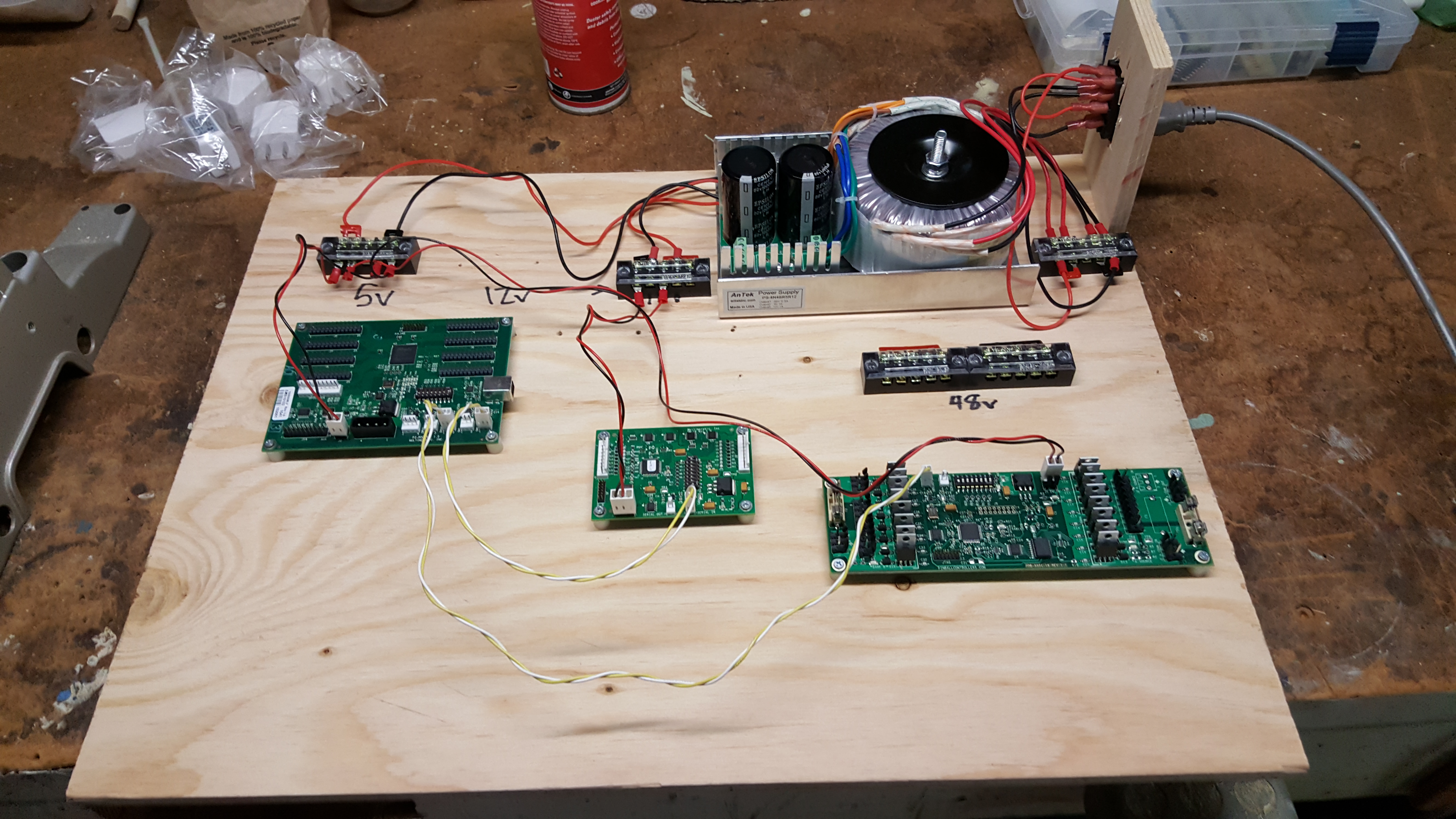
I have a 10 amp fuse between me and the wall for the net total power.  I have 4 amp fuses between the banks of 8 solenoids and the power.  The power supply rated for 8amps on 48v line.

The beefiest solenoids in the whole thing are the flippers.  Flippers are funny in that they are dual wound.. there are two magnetic coils there.  One powerful one for the stroke of the flipper, and a weaker one for when you hold the button down continuously to catch or other fancy flipper work.   It activates at the “end of stroke” of the flipper.

The primary coil has a resistance of only 4.7 ohms.. if one gets stuck on instead of transitioning to the hold coil, it would be roughly 10 amps @ 48V (Ohm’s Law).  Which makes 18 AWG a good choice to be in the clear for a stuck on, and for some reason the fuse failed, situation.

Link to exhaustive list of solenoids used in pinball machines over the years, with their resistance.  https://www.flippers.com/coil-resistance.html

At any rate, I started this post thinking I was just going to use 22AWG for all wiring. The justification was that if the fuses blow appropriately, then a coil shouldn’t ever exceed the 5-7 Amps for long enough to overheat the wiring.   After working through this a bit more for this post, I think if I were to standardize on just one wire gauge, 20AWG would be better suited, with a little more margin for the high power devices without getting so big for the simple switches and things which have no current.   For me, since I went “all in” on 22 AWG, I’m now ordering a 5 color 25ft pack of 18 AWG vs a full rainbow of the other colors.

Spades / Ring Terminals

Just random stuff from hardware store.  I did realize that these terminal blocks have different spacing between the studs and you can buy spades that don’t fit your terminal blocks.

Crimper

Amazon cheap racheting crimper.  I got this for cheap Dupont style connectors but working well on all of the above. I do have to use the size down on the terminals that 22AWG is the lowest end of the range.

HT-225D Full Cycle Ratchet Crimper

I am slowly getting better at crimping. However, I still usually follow up a crimp with a quick nip of solder.  Someday I will not need this assurance but not yet!

Pinball · Uncategorized

The story so far

I kicked off the pinball build about 3 weeks ago.  I am trying to get to the point of 4 flippers flipping on two playfields as the first major milestone.  There’s a few things to get there:

  • Power supply – the flippers are powered by solenoids that usually run on 48-70v DC. I’ve chosen 48V DC as that’s the highest voltage that is still considered ‘low voltage’ from a safety point of view.  Other than the high voltage DC; both 12V and 5V is needed to power the computer, and the pinball electronic interface (P3-ROC, driver(outputs) module, switches (inputs) module).
  • Power distribution – with all these different voltages , need ways to get them to all the different areas.  Using terminal blocks.
  • Flipper Assemblies – bought from pinballlife.com
  • Flipper Buttons – the player buttons to each side to activate flippers
  • Computer – got a Low power Intel computer (AsRock q1900), hard drive, ram, case, etc
  • Software – linux operating system running Mission Pinball Framework. The bare minimum software here is pretty easy in this framework: flipper button pushed = flipper activated. It’s actually a bit more complicated but that’s the gist.

Over the last couple weeks have bought all the parts and gotten some initial testing done.  This weekend was getting the power and power distribution sorted, which I am nearly happy with.

There is a lot of room there left where additional boards, wiring and the computer will end up.  But, there’s enough there right now to get flippers going.  And no smoke was let out!

Uncategorized

Testing.. testing

Long story short… I have had a long list of hobbies .. most come and go.   However, as I take on this next one, I figured it would be a good idea to write some things down, possibly get some peer pressure to actually finish.. as this one is pretty ambitious.

I have just started a project to build a pinball machine.   Specifically a “head to head” style that has never been a commercial success with few examples.  The ones I’ve been able to play are :

Why this commercially unsuccessful style of game?  Well, I just thought it would be something different and maybe more fun for non-pinball people.  There’s not been a lot of activity in this area since late 90s and I think there could be some fresh ideas here.

Also, it’s important to give credit here; there was significant googling before I thought I could even think of this task; the big confidence boosters :

  • Pinside – Currently the most popular forums for pinball discussion.  There have been many home brew build threads on there.  From what I can tell about the home brew build threads.. seems like the average is about 2 years :-O
  • Pinball Controllers / Multimorphic – Gerry has been selling USB based pinball control hardware for many years now.  Additionally, this hardware has made it into some commercial games, such as The Big Lebowski by Dutch Pinball
  • Pinball Makers – Lots of lessons learned, 3D Cad files, tools, dimensions, etc from other pinball makers
  • Mission Pinball Framework – There are a few pinball software frameworks, and having evaluated a few of them.. this one is the most active and they seem pretty serious for a project that nobody makes any money off of  (automated unit tests!)

There will be more, but these are the ones that have helped kick this off