Uncategorized

June Update

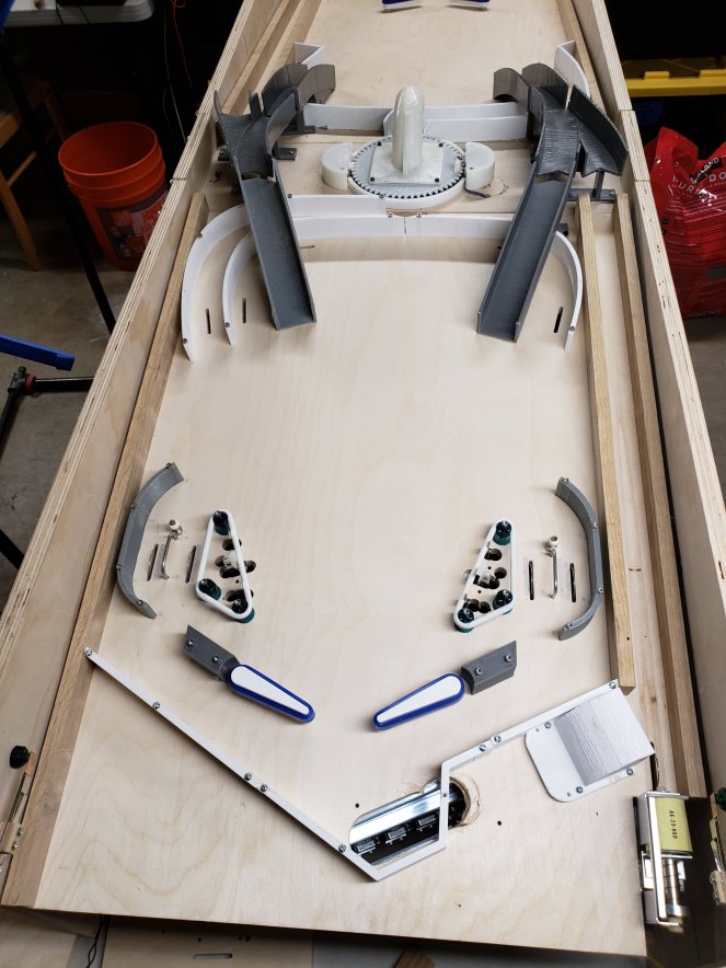
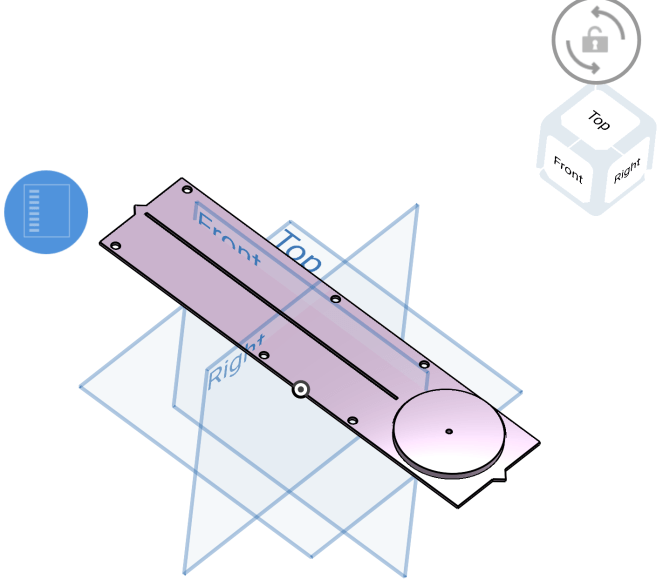
Have been struggling with what the top 1/3 of the game is going to be like.

20180520_164441

This was the first pass..  two pop bumpers behind a set of 3 drop targets.  This didn’t work at all in practice due to the amount of space on the underside required to mount the assemblies.   So, it’s fitting that this one looks like a Cyberman crying.  also note that I tried to do this the partial cut / coupon way as well, conserving wood as a iterate.

Since then i’ve been looking around at other games for ideas.  Right this second I’m looking at copying a feature from Spiderman home edition / Supreme pinball.

https://www.ipdb.org/showpic.pl?id=6438&picno=71510

The Doc Ock zone is a set of 3 drop targets making the side of a triangle with a target at the opposite vertex.   Experiments with that are ok except there’s little room for much else in the upper playfield area then so not sure if i’m quite happy with that either.

Lots of mulling about right now.. hopefully will have some inspiration soon.  Guess I need to go out and play some more location games to see if there’s something else I want to poach.


Uncategorized

April update

One playfield is wired up on the lower half now.

And now in the game.

So now reprinting a couple things today so I can play 1 side of the game only. Will be spending some time with software in coming days.

From a physical game point of view, need to sort out the sides and the middle center. Pop bumpers? Drop targets? Magnet? I’ll get serious about that after I can get what’s currently installed working.

Uncategorized

March update

So we got our hobby CNC in a few weeks ago and have been starting to cut out a playfield to start dialing in the CAD and playing it.

20180311_183719.jpg

With this I got the next round of pinball parts in.. i just go one side of mechanisms worth as I’m not sure yet what I want to do for everything.  But once hooked up one side of the game will have ‘the basics’ – flippers, slingshots, loops w/ switches, inlanes and outlanes.

20180326_070101.jpg

Also built a rotisserie this weekend out of black pipe from home depot.  This allows you to quickly spin the playfield around to make assembly quicker and easier on your back.

20180325_184535

Right now i’m making some coupons to dial in the inlane/outlane geometry as my CAD didn’t account for the thickness of the rubber rings.   Think I’ve got maybe one or two more attempts to go.  This is after I cut the playfield, then filled some holes, cut again and then realized I should walk before I run and just cut the sections I’m playing with on scrap.

20180326_065444

I went to Arcade Expo 4.0 in Banning a week ago and that gave me some ideas.  One thing I’ve been realizing is that my playfields are feeling short.  I mean, I made them shorter than standard (30″ vs 41-46″).  Guess what, 10″ is a lot of inches shorter!

Anyways, will see if i make them longer or not..  I wanted the entire game(so 2x playfields + 6″ center section) to be ~6 feet for 3 reasons:

  • the game itself isn’t hugely long like a shuffleboard table as that seems ridiculous
  • the baltic birch plywood is easily available in 30″x24″ panels from Rockler.. sometimes they go on sale for under $10 so seemed like it was worth restricting the overall length to that.
  • home CNC machine max cutting area is 31×31″ so to cut something longer i’d have to slide the piece during the cut.  Given i’ve had some issues already trying to recut the same piece, alignment can be a bit of a challenge.  but if i went to 36″ or something maybe we’re just talking about 1 or 2 cuts that have to be done in the 2nd pass.

I will say my enthusiasm level is increasing as it starts to look like something and I get to something that can be played.

A side note.. I have, for now, switched to printing PETG plastic instead of ABS.  My print failure rate was very high with ABS, for all manner of reasons but the stuff does like to warp as it shrinks when it cools more than most.   PETG isn’t quite as strong (especially given I can vapor smooth ABS) but I think “good enough”, and prints WAY easier.  I haven’t had a single failed print and i’ve just about finished my first spool.   So, maybe my ‘final’ editions I go back and do ABS so I can get the utmost strength, but for test iterations this is way better.

Uncategorized

1 ramp printed

Finalizing CAD of the ramp.. I ended up bringing all my playfield parts over from OnShape to fusion 360 so I could really adapt the flow of the ramp to the two playfields more precisely, saving on iterations (in theory)

full playfield

After tweaking it, and then trying to get my 3d printer to cooperate, I at least have one of them printed now.  And due to me running out of white ABS filament, can see how i broke the ramp up so that both playfields can still be lifted / rotated away from the center bridge section and not have to disassemble anything.

Of course, things don’t line up perfectly.. one grey section is perfectly aligned to the white junction, and the other two are low (not even on the same playfield).  I am thinking though a 1″ steel ball bearing isn’t going to care about 1mm offset, but i may just shim up the low ones with a washer or two when ready to screw them in.

Hope to print the second ramp this weekend, and Acetone vapor polish all of it.. these things will take a beating and feel the acetone bath really fuses the layers together a lot better than printing alone.

Uncategorized

Progress report – Holiday 2017

Changed jobs at first of December, and then we had planned to go back East for Christmas but our dog came down with pneumonia so we ended up being in town after all.

So, tried to make good use of that time.  With the central mechanism in wired and in place finally started working on some play-field layout elements.   I did a quick sketch in CAD and then transferred it to the playfields of just the top section.

Capture

Also, I’m trying out Fusion 360 as there is a direct plugin from that to the Shaper router thing once that shows up.

To mock this up using foam core and hot glue.  This is surprisingly sturdy.. I tried to pull a piece up after gluing it down and took off the top veneer of the wood with me.

Anyways, I am suspecting the inner loop is going to be too weird of an angle and the ball is not going to travel smoothly along it.  I had hoped to “play” this to try it out but one thing is clear already is that when you bend the foam core it gets creases in it.. which is already not a smooth surface.   I’m going to look into this more.. maybe covering the walls with packing tape will smooth it out enough for the ball to move along the path.

The ramp has been eating away hours and hours.   I did the foam core mockup, which was pretty useful.

But then it was trying to turn that into CAD so i can 3d print it where I got totally lost for a week and a half.  Things with lots of curvature in multiple dimensions is not straightforward it seems.   I had one approach (sweeps) that got me 95% there quickly, but impossible to bridge the last 5%.  I had a different approach that fixed that 5% but then sucked after that.   But, after starting over again and being more careful with the ‘sweep’ approach, I now have something that should be pretty close to the foam ramp.

However, experience with the central mechanism says i will probably need a few goes at this.   I did print just the middle section of an earlier attempt which came out pretty good

20180111_0737001058709610.jpg

Hoping this weekend to print out 1 full ramp, figure out what needs to be adjusted and if i’m super lucky print out a second one; but these prints take quite a while, so not holding out hope for the 2nd iteration.


Uncategorized

Thanksgiving – progress?

With there being a 4 day weekend here,  I hope to make a bit more progress on the build.   Over the last week or two I’ve completed the wiring harness for the center mechanism on the test jig

20171114_074937.jpg

And so now I have a completely wired:

  • 8 Ball Trough w/ Jam Switch (if a ball fails to exit, can detect if there’s now 2 vertically stacked on each other
  • Opto Detectors on the Left and Right subway entrance so I can detect which side the ball enters from
  • Ejector Solenoid
  • Stepper motor
  • Homing switch for stepper – in work, I have the cabling, I forgot how I had it hooked up to the trinamics steprocker board; will capture a schematic next time or maybe go reference some of the older pictures .. i knew there was a reason I did this blog.

Which leads me back to the less fun part… Software.. 😉

The Mission Pinball framework is very config file (YAML) heavy.  So the firs step is getting your config files all setup for which IO pins are which functions, and I’ve also used this to capture my color coding.  I am ashamed that with 11 colors of wire, I’ve discovered that I reused the same color in connectors with as little as 8 pins.. obviously, doing a lot of this early before I’ve had coffee isn’t paying off.

I’m using Visual Studio Code for editing..  on Linux.. yep, Microsoft has released a stripped down Visual Studio for Linux now, that’s free.  Has lots of language highlighting, plugins for python, intellisense, and even understands python unit test frameworks.

Screenshot from 2017-11-23 14-36-13

I’ve got everything detected now and am going to work this weekend to bring it together with the stepper.  Ideally, this goes smoothly and something resembling a mode involving the contraption exists by the end of the weekend.

After that it’ll be drilling the holes into the real game and moving from the test fixture.   So, maybe by the end of the holidays can maybe play something?  We’ll see, trying not to get overly ambitious.

Uncategorized

Wiring up the ball trough

Ok after all the 3d printing of the subway / ramp assembly for the turret, I moved on to wiring up the ball trough.   There are 7 microswitches on the trough itself (to count 7 of the 8 balls), and two optos (ball 1 and ‘jam’ – if a ball gets stuck).    Then, I added an opto on each subway to detect which side the ball arrived on.. this will be key.

First up was creating a power supply for the optos.  Opto switches are a combination of an IR LED (like what’s in your TV remote) that needs a decent amount of current for a LED (70-100ma).   Creating that much power required creating a small circuit board.

I got a cheap 48v to “whatever” DC converter (to use 5 volts on the LEDs) and then built the circuit.

20171102_065604.jpg

After that was wiring up the individual switches on the stock ball trough

20171105_070413.jpg

And into a harness that I can attach to the SW-16 p-roc switch board.

20171105_073748.jpg

And from there, here’s the whole thing, with the optos also mounted to the 3d printed subway.    Now i need to mount all this stuff back to my test jig.  I’m starting to realize things are going to be a bit crowded on the thin strip of wood.

20171105_190731.jpg

Side note, we were in Seattle last weekend and I got to play a fathom.. I hope to copy many of the elements from this 80’s classic.   This particular game was well restored.

20171028_211021.jpg

I had my credit card in there so I can take accurate dimensions from this photo.  The sidelands are unique on Fathom as the far left (outside) lane is the ‘safe’ lane, the inner outlane falls straight through.  I plan to try this out on my game.   And don’t worry, the credit card number is on the back 😉

Uncategorized

ABS Vapor smoothing

This last week or so was focused on getting good prints from ABS plastic. ABS is stronger than other plastics but super hard to print.. it loves to warp as it prints. So if it even holds onto the bed its no longer dimensionally accurate.

Thru a lot of trial and error I got a full set of parts made. So this weekend I was playing around with a process I’ve not tried before which is vapor polishing. If you place an ABS part into acetone vapor, it softens and melts slightly. Thus much improves surface finish as well as better bonds the layers.

I used a bucket with foil lid to do this. I put a paper towel in bottom, soaked in acetone, then I put a foil square on that to rest the part on without direct contact to soaked paper. I closed up bucket and put that on the heated bed of my printer set to 80C. The warmth gets the acetone into vapor a bit better.

All in all impressed with results.

The blue parts are pla, not smoothed.

I also printed some drill guides. It is extremely critical the parts below the wood align exactly with the parts above the wood.. so I designed and printed some templates that fit into the 2″ hole and set the drill holes from there.

So, that’s another handy thing one doesn’t necessarily think about when getting a 3d printer but sure is handy.

Uncategorized

Finally a little progress

Finally, after an avalanche of failed prints I have some basic amount of sucess with the ball turret.

Can spin all the way around and balls exit.

And able to reload from either side.

So need to see if I can improve the firing a bit, I’d like to get it to totally clear the troughs vs occasionally falling into them.

Uncategorized

Tools – Handheld CNC?


Ok so while I’ve slowed down (again) on progress of my pinball machine, I’ve gotten interested in a new startup pre-order tool.    Me and pre-orders have been extremely lucky.. I am currently one of ~50 people with a Big Lebowski pinball machine right now due to a pre-order (people 51-300 are still waiting due to contract manufacturing disputes).   I also have a 3D printer that was on clearance after a failed kick starter for $350 (was $1000).  So, I’ve been very successful, but also some near misses.

Yet, I go back into the frey once again.   This time, the Shaper Origin.. handheld CNC.   It’s a handheld router with computer vision and augmented reality thrown in to give you a CNC like experience where you and your person is the XYZ robot that moves the head around.  To do this, you do have to cover the workpiece with proprietary tape so it can triangulate it’s position.

Website:  https://shapertools.com/

Here’s their promo video

Now, the very first question that came to mind after watching some of the initial videos was your hand motion is going to make this whole thing imprecise.  However, there are actually tiny servos that move the spindle +/- 1/4″ or so on your behalf to keep the lines straight and on the tool path.  Highlighted here:

Here’s some other videos:

  1. The most recent video , a Q&A with the CEO.  This answered a couple questions for me like Z travel height.

2. This is in response to a Q&A (original Q&A here: http://www.core77.com/posts/55712/How-Practical-is-the-Shaper-Origin-Self-Correcting-Router


Appealing to me is that i was otherwise looking at several hobbyist home CNC machines.. they are also priced around $1800 (Xcarve and Shapeoko) but are limited in size, 1m^2 or so.. so less than 4 feet.  Plus, storing a 4’x4′ dedicated cnc router takes a lot of space in garage.  I still have access to the makerplace giant one for more serious work.

And, also, if you order one for some reason, they are doing a promotion right now where they give people that have preordered a link that gives other people $100 off (this effectively is Free Shipping), but it also gives the provider of the link an additional $100 off per unit.  A pyramid scheme of discounts 😉   But, since I just pulled the trigger, here’s mine:

https://preorder.shapertools.com/ref/H5MTC000D